Monday, September 28, 2015
Friday, August 28, 2015
RAID controller
As RAID controller is responsible for the operations on RAID array drives, it is very important to have an enterprise class controller for enhanced performance, increased reliability and fault tolerance. Considering the business requirement and budget, you can choose a RAID controller. Here I will be explaining about DELL Power Edge RAID Controller (PERC). When choosing a controller, there are few critical hardware features that affect performance to keep in mind :
- Read policy
- Write policy
- Controller cache memory
- CacheCade
- Cut-through I/ O
- FastPath
Saturday, August 8, 2015
How to calculate total IOPS supported by a disk array
IOPS stands for input/ output operations per second.
Consider a RAID array with 4 disks in RAID 5. Each disk is 4TB 15K SAS drive. We can use the below formula for calculating maximum IOPS supported by the RAID array.
Raw IOPS = Disk Speed IOPS * Number of disks
Functional IOPS = (Raw IOPS * Write % / RAID Penalty) + (RAW IOPS * Read %)
No: of disks = 4 (4TB 15K SAS)
IOPS of a single 15K SAS disk = 175 - 210
RAID penalty = 4 (for RAID 5)
Read - Write ratio = 2:1 (say we have 66 % reads and 33 % writes)
From the above details :
Raw IOPS = 175 * 4 = 700
Functional IOPS = (700 * 0.33 / 4) + (700 * 0.66) = 519.75
Therefore, the maximum IOPS supported by this RAID array = 520
The above calculation is entirely based on assumption that the read - write ration is 2:1. In real time scenarios it may vary depending on the type of workload. That means workload characterization is also important while calculating maximum IOPS value supported by your RAID array. It also depends on the type of RAID, as penalty will be different for different type of RAID. Disk type (SSD, SAS, SATA etc), disk RPM and number of disks also affects the total IOPS value.
From this we can conclude that, if your current IOPS usage is closer to the maximum IOPS supported, then you have to be very cautious as it may lead to I/O contentions due to heavy workloads causing high latency and performance degradation to your storage server.
Thursday, July 9, 2015
Server load balancing using KEMP Load Master
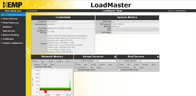
This article explains the basic configuration steps for load balancing multiple web servers using KEMP load balancer. In my setup, I've two web servers (INVLABSWEB01 and INVLABSWEB02) which are load balanced using a KEMP Load Master. For the purpose of testing I've used a virtual load master appliance (VLM-5000). After the installation is complete, you have to activate the license. Once you are done with that, you can get to the home page of the load master using a web browser as shown below.
 |
| Home page |
Now you have to add a virtual service. Click add new, provide a virtual address, give it a name, select a protocol and click add this virtual service.
 |
| Add new virtual service |
Select a service type. Check the box to activate the service.
Expand standard options. Select the options as shown below. If you don't select Force L7 option, then the virtual service will be forced to Layer 4. Transparency can be enabled or disabled depending on the use case.
If persistence mode is enabled, the same client will subsequently connect to the same real server depending the mode selected. And there is a timeout value, that can be set which determines for how long this particular connection is remembered.
Scheduling method determines the method by which the load master selects a real server for a particular service. There are several methods like round robin, weighted round robin, least connection, resource based (adaptive) etc. Here I have selected round robin.
Scheduling method determines the method by which the load master selects a real server for a particular service. There are several methods like round robin, weighted round robin, least connection, resource based (adaptive) etc. Here I have selected round robin.
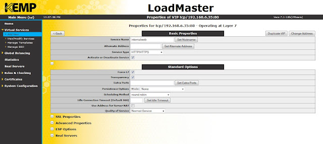 |
| Basic properties and standard options |
If you want to enable SSL acceleration, that can be done here.
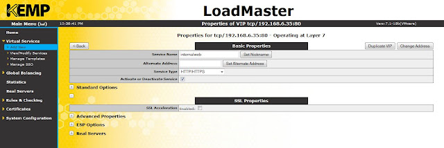 |
| SSL acceleration |
Advanced options like enabling caching, compression, access control etc can be done here.
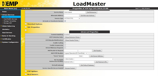 |
| Advanced properties |
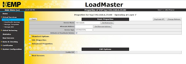
Edge Security Pack (ESP) feature can be enabled in this option.
 |
| ESP feature |
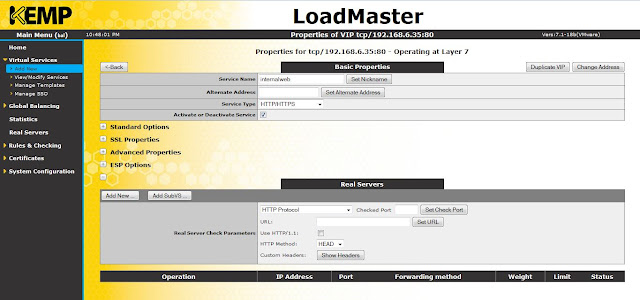
Click add new to add real servers to the virtual service (VS).
 |
| Real servers |
Provide real server address, port number and click add this real server.
 |
| Add real server |
Similarly, I've added two web servers (192.168.6.30 and 192.168.6.31) here.
 |
| Real servers |
Click on view/ modify services to view the VS that you have just created.
 |
| Virtual services |
Click on real servers to view the real servers (INVLABSWEB01 and INVLABSWEB01).
 |
| Real servers |
Now, both of my web servers are load balanced. If you want to disable any of the servers from the load balancer, click disable button for the respective server.
Reference :
Kemp Technologies
Reference :
Kemp Technologies
Wednesday, July 8, 2015
Multi-Master Model and FSMO Roles
Consider an enterprise with multiple Domain Controllers (DC). A multi-master enabled database like Windows Active Directory (AD), allows to update changes to any DC in the enterprise. But, in this case there are chances/ possibilities of conflicts which may lead to problems. As AD role is not bound to a single DC, it is referred as a Flexible Single Master Operation (FSMO) role. Currently in Windows there are 5 FSMO roles. These roles prevent conflict operations and are vital for handling the smooth operation of AD as a multi-master system. Out of the 5 FSMO roles, there are 2 forest wide roles per forest and 3 domain wide roles in each domain.
Forest wide roles
-Schema master : controls all updates and modifications to the schema (eg : changes to attributes of an object).
-Domain naming master : responsible while adding or removing a domain in a forest.
Domain wide roles
-RID master : allocates Relative IDs (RID) to DCs within a domain. When an object is created it will have an SID, which contains a domain SID (same for all SIDs created in the domain) and RID which is unique to the domain.
-PDC emulator : responsible for time sync, password changes etc.
-Infrastructure master : responsible for updating references from objects in its domain to objects in other domains. Infrastructure master role should not be on the same DC that is hosting the Global Catalogue (GC), unless there is only one DC in a domain. If they are on the same server, infrastructure master will not function, it will never find data that is out of date and so will never replicate changes to other DCs in a domain. If all DCs in the domain hosts a GC, then it doesn't matter which DC has the infrastructure master role as all DCs will be up to date due to the GC.
If you want to transfer FSMO roles from one DC to another, you can follow the below steps.
 |
| To check current FSMO status |
 |
| Steps before role transfer |
Use ntdsutil to transfer the roles. You have to connect to the server to which you want to transfer the role. Above screenshot explains this whole process.
 |
| Transfer roles |
Click Yes to transfer the role and then transfer all roles one by one.
 |
| FSMO status after role transfer |
Now all roles are moved from INVLABSDC02 to INVLABSDC01.
Sunday, May 17, 2015
Port forwarding in Windows
An example of port forwarding is shown below :
C:\Windows\system32>netsh interface portproxy add v4tov4 listenaddress=192.168.18.43 listenport=5555 connectport=80 connectaddress= 192.168.87.142 protocol=tcp
C:\Windows\system32>netsh interface portproxy add v4tov4 listenaddress=192.168.18.43 listenport=5555 connectport=80 connectaddress= 192.168.87.142 protocol=tcp
Here, 192.168.18.43 is the IP address of my local computer and 192.168.87.142 is the IP address of a virtual machine running inside my local machine. The above command will port forward all requests coming to 192.168.18.43:5555 to 192.168.87.142.
Sunday, May 10, 2015
Spinning up an OpenStack cloud instance using TryStack
TryStack is a free way to try OpenStack. Its an OpenStack sandbox. That means TryStack is a testing environment only. You cannot use it for setting up your production servers. You can get a free account in TryStack by joining their Facebook group. As this is a testing facility there are several limitations in it. The server instances that you launch inside TryStack will be available for 24 hours only. You cannot upload your own server images to it, you can only select the available images in it.
After joining their Facebook group, you can start using TryStack with your Facebook login.
You will be able to create maximum of 3 instances, 6 VCPUs, 12 GB of RAM, 4 Floating IPs etc.
Before creating your first cloud VM, you need to do some initial configurations like creating a network, adding a router, defining security group etc. This is explained below.
Creating a network :
Click on create network tab, and enter a name, click next.
Enter network address with a subnet mask and gateway IP. Click next.
Enter the following details as shown below and click create.
A new network (192.168.10.0/24) named private is now created.
Now there should be a router to enable communication between your internal and external network. So click on create router tab. Enter a router name and click create router.
A router will be now created as shown below. Mouse over the router and you will get options to add an interface.
Click on add interface, select the private network that you have created earlier from the drop down menu and enter the details as shown below and click add interface button.
Now the router is connected to your private network through the interface 192.168.10.1
Next step is to connect the router to external network. Select the routers tab from the left hand side menu.
Click set gateway button, select external network and click set gateway.
Now, check your network topology and you can see that the internal and external network is connected with the router.
Next step is creating a security group and defining rules. Select access & security from the left hand side menu and then click on create security group.
Enter a name and description and click create.
Now, click manage rules tab of security group that you have just created (securitygroup1). If there is any rule which is already present, select all and delete them. Click add rule. You will get a window as shown below to add your custom rules.
The above rule just allows ingress HTTP traffic. Similarly we have to allow ingress as well as egress traffic for HTTP, HTTPS, SSH and ICMP. Once all the rules are added, it will look like the below screenshot.
Next you have to create a key pair.
Click on import key pair. Here I am using Putty key generator to generate the keys. Click generate button and a key pair will be generated. Save the private key locally in your machine. It will be a .ppk file. As shown in the below screenshot, copy the public key from Putty key generator and paste it in public key text field. Give a key pair name too.
Click import key pair and it will be generated as shown below.
Next step is allocating floating IPs.
Click allocate IP to project.
Click allocate IP and now a floating IP will be allocated.
Now you are all set to create your first instance. Select instances tab and then click launch instance.
Do not click launch now. Click on the next tab (access & security).
Select the key pair and security group that we have created earlier. Click launch. You have just created your first instance.
From the above screenshot, you can see that the VM has an internal IP address. Inorder to access this VM from public, you have to associate it with a floating IP. Follow the below screenshot.
Click associate floating IP.
Select IP address from the drop down menu and click associate. Now you can see that the floating IP is mapped to the private IP of the VM.
Status of your instance and network topology is shown below.
You can PING to your cloud instance.
You can SSH into your VM using Putty. Enter IP address of the VM.
Under connections tab, select data and enter username as fedora. This is the default user name for fedora21 cloud image.
Browse and select the private key file that you have saved locally in your machine and click open.
You are now successfully connected to your OpenStack cloud instance through SSH.
Final overview from your OpenStack dashboard is also shown below.
Thank you and all the best in creating your first OpenStack cloud instance. Cheers!
Subscribe to:
Comments (Atom)


