Saturday, October 24, 2015

Enabling jumbo frame on Hyper-V 2012 R2 Core NIC using powershell

Enabling jumbo frame on a NIC using powershell is shown below :

Enabling jumbo frames using powershell


To list advanced properties of NIC3 : Get-NetAdapterAdvancedProperty -Name "NIC3"

To change jumbo mtu to 9000 : Get-NetAdapterAdvancedProperty -Name "NIC3" -RegistryKeyword "*jumbopacket" | Set-NetAdapterAdvancedProperty -RegistryValue 9000


Jumbo frames

Jumbo frames are Ethernet frames with more than 1500 bytes of payload. Generally, jumbo frames can carry up to 9000 bytes, but variations do exist. Enabling jumbo frames in specific cases (say, in your Storage Area Network) can improve performance and network throughput. But, if you are enabling it, all devices connecting it including the source, destination and other devices in between like switches etc must support jumbo frames and should be enabled.

Enabling jumbo frames on a VMware virtual network adapter (vmxnet3) is shown below :

Jumbo Packet on vmxnet3 adapter
Steps to enable jumbo frames on a VMware vSphere 4.1 vSwitch is shown below :

List vSwitch
 By default it is 1500 MTU. Say, you want to change vSwitch1 to 9000 MTU. It can be done as follows :

Enabling jumbo frame with MTU 9000 on vSwitch1
You can verify connectivity after enabling jumbo frames by specifying packet size using ping command as given below :

Verifying jumbo frames


Creating VHD/ VHDX templates

Templates can save you lot of time, instead of building a server from scratch. Following are the steps to create a VHD/ VHDX template that can be used on Hyper-V servers.

1.Create a virtual machine (say Windows Server 2008 R2 with 80 GB hard drive)
2.Make sure you create fixed disk
3.Install OS
4.Install Windows updates
5.Install Hyper-V integration services
6.Install any applications as per your requirement

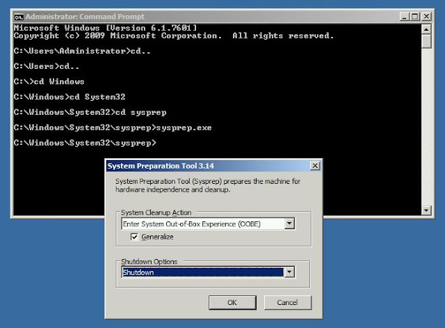
Once you are done with all the above steps, now its time to sysprep your machine. This is shown below :

sysprep

Make sure you check Generalize and shutdown options. Once the system completes sysprep operation, it will automatically shutdown. You can now take a copy of this VHD disk, rename it as you wish and save it to a location where you keep your templates. Also, make sure to make this file as read-only, so that you can avoid booting it up accidentally.

Note : You can create VHD templates for OS earlier than Windows Server 2012 and VHDX templates for Windows Server 2012 and later.

Friday, October 2, 2015

Monday, September 28, 2015

Ports on FC Switched Fabric (FC-SW)

The diagram given below gives a brief idea about the different types of ports on a Fiber Channel Switched Fabric.

Ports on FC Switched Fabric


Friday, August 28, 2015

RAID controller

As RAID controller is responsible for the operations on RAID array drives, it is very important to have an enterprise class controller for enhanced performance, increased reliability and fault tolerance. Considering the business requirement and budget, you can choose a RAID controller. Here I will be explaining about DELL Power Edge RAID Controller (PERC). When choosing a controller, there are few critical hardware features that affect performance to keep in mind :
  • Read policy
  • Write policy
  • Controller cache memory
  • CacheCade
  • Cut-through I/ O
  • FastPath

PERC Series

PERC H810 - high performance RAID controller that can be connected to JBOD

PERC H710P - ideal for implementing hybrid server platforms based on SAS HDDs with high performance and enterprise class reliability

PERC H310 - entry-level RAID controller (no cache)

Reference :
Dell
Microsoft

Saturday, August 8, 2015

How to calculate total IOPS supported by a disk array

IOPS stands for input/ output operations per second. 

Consider a RAID array with 4 disks in RAID 5. Each disk is 4TB 15K SAS drive. We can use the below formula for calculating maximum IOPS supported by the RAID array.

Raw IOPS = Disk Speed IOPS * Number of disks

Functional IOPS = (Raw IOPS * Write % / RAID Penalty) + (RAW IOPS * Read %)

No: of disks = 4 (4TB 15K SAS)
IOPS of a single 15K SAS disk = 175 - 210
RAID penalty = 4 (for RAID 5)
Read - Write ratio = 2:1 (say we have 66 % reads and 33 % writes)

From the above details :

Raw IOPS = 175 * 4 = 700
Functional IOPS = (700 * 0.33 / 4) + (700 * 0.66) = 519.75

Therefore, the maximum IOPS supported by this RAID array  = 520

The above calculation is entirely based on assumption that the read - write ration is 2:1. In real time scenarios it may vary depending on the type of workload. That means workload characterization is also important while calculating maximum IOPS value supported by your RAID array. It also depends on the type of RAID, as penalty will be different for different type of RAID. Disk type (SSD, SAS, SATA etc), disk RPM and number of disks also affects the total IOPS value.

From this we can conclude that, if your current IOPS usage is closer to the maximum IOPS supported, then you have to be very cautious as it may lead to I/O contentions due to heavy workloads causing high latency and performance degradation to your storage server.