Showing posts with label cluster. Show all posts

Sunday, April 18, 2021

vSphere with Tanzu using NSX-T - Part7 - Enable workload management

In the previous posts we discussed the following: 

Part1: Prerequisites

Part2: Configure NSX-T

Part3: Edge Cluster

Part4: Tier-0 Gateway and BGP peering

Part5: Tier-1 Gateway and Segments

Part6: Create tags, storage policy, and content library


We are all set to configure and enable workload management. Before stepping into the configurations I just want to give an overall picture of vSphere with Tanzu architecture and different components. 


Once you enable workload management, the vSphere cluster will transform to a supervisor cluster. The supervisor cluster consists of 3 supervisor control plane VMs, and the ESXi hosts that act as worker nodes too. Now you can run traditional VMs, and containers side by side. You can run the containers as native vSphere pods directly running on the ESXi hosts, or you can deploy Tanzu Kubernetes clusters in VM form factor on the vSphere namespace and then run container workload on them.

Following are the steps to enable workload management:

  • Login vCenter - Menu - Workload Management.
  • Click Get started.
  • Select NSX-T and click next.

  • Select the cluster.

  • Select a size and click next.

  • Select the storage policy and click next.

  • Provide management network details and click next.

  • Provide workload network details and click next.

  • Add the content library and click next.

  • Click finish.

  • This process will take few minutes to configure and bring up the supervisor cluster. In my case, it took around 30 minutes to complete.
  • You can see the progress in the vCenter UI.


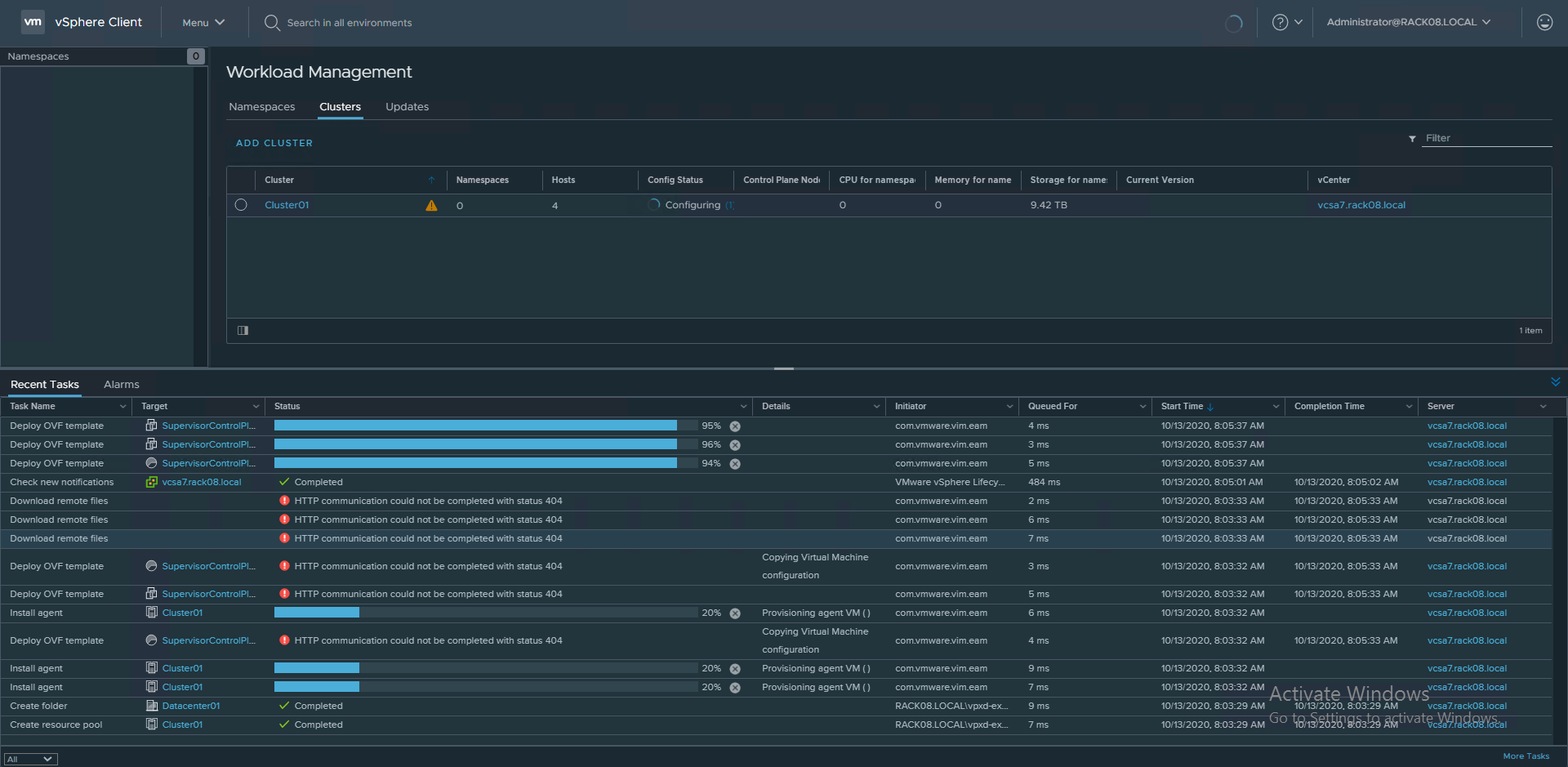
  • You can now see the supervisor control plane VMs are deployed.


Workload management is now enabled and the vSphere cluster is transformed to a supervisor cluster. Let's have a look at the objects that are automatically created in NSX-T.
  • You can see a T1 Gateway is now provisioned.

  • Multiple segments are now created corresponding to each namespace inside the supervisor control plane.

  • Multiple SNAT rules are also now in place for the newly created T1 Gateway, which helps the control plane Kubernetes objects residing in their corresponding namespaces to reach the external network/ internet. It uses the egress range 192.168.72.0/24 that we provided during the workload management configuration for address translation.

  • You can also see two load balancers attached to the T1 Gateway:
    • Distributed Load balancer: All services of type ClusterIP are implemented as distributed load balancer virtual servers. This is for east-west traffic.
    • Server load balancer: All services of type Loadbalancer are implemented as server load balancer L4 virtual servers. And all ingress is implemented as L7 virtual servers.

  • Under the server load balancer, you can see two virtual servers. One for the KubeAPI (6443) and the other for downloading the CLI tools (443) to access the cluster.

Note that this newly created T1 Gateway (domain-c8:6ea515f0-39da-431b-93bf-0d6a5e4a0f77) is connected to the T0 Gateway for external connectivity through BGP.
 
The next step is to create namespaces, and you can then create Tanzu Kubernetes clusters on it. Usually, the vSphere administrator will create namespaces for developers and provide the access so that they can either deploy TKG clusters, vSphere pods, or VMs on the respective namespace. We will cover all these in the next part. 

Hope it was useful. Cheers!

Sunday, February 7, 2021

vSphere with Tanzu using NSX-T - Part4 - Tier-0 Gateway and BGP peering

In the previous posts we discussed the following: 

Part1: Prerequisites
Part2: Configure NSX-T
Part3: Edge Cluster


The next step is to create a Tier-0 Gateway, configure its interfaces, and BGP peer with the L3 TOR switches. Following is a high-level logical representation of this configuration:


Configure Tier-0 Gateway


Before creating the T0-Gateway, we need to create two segments.

  • Add Segments.
    • Create a segment "ls-uplink-v54"
      • VLAN: 54
      • Transport Zone: "edge-vlan-tz"
    • Create a segment "ls-uplink-v55"
      • VLAN: 55
      • Transport Zone: "edge-vlan-tz"

  • Add Tier-0 Gateway.
    • Provide the necessary details as shown below.

    • Add 4 interfaces and configure them as per the logical diagram given above.
      • edge-01-uplink1 - 192.168.54.254/24 - connected via segment ls-uplink-v54
      • edge-01-uplink2 - 192.168.55.254/24 - connected via segment ls-uplink-v55

      • edge-02-uplink1 - 192.168.54.253/24 - connected via segment ls-uplink-v54
      • edge-02-uplink2 - 192.168.55.253/24 - connected via segment ls-uplink-v55
    • Verify the status is showing success for all the 4 interfaces that you added.

  • Routing and multicast settings of T0 are as follows:

    • You can see a static route is configured. The next hop for the default route 0.0.0.0/0 is set to 192.168.54.1. 

    • The next hop configuration is given below.

  • BGP settings of T0 are shown below.

    • BGP Neighbor config:

    • Verify the status is showing success for the two BGP Neighbors that you added.

  • Route re-distribution settings of T0:

    • Add route re-distribution.
    • Set route re-distribution.

Now, the T0 configuration is complete. The next step is to configure BGP on the Dell S4048-ON TOR switches.

Configure TOR Switches


---On TOR A---
conf
router bgp 65500
neighbor 192.168.54.254 remote-as 65400
#peering to T0 edge-01 interface
neighbor 192.168.54.254 no shutdown
neighbor 192.168.54.253 remote-as 65400
#peering to T0 edge-02 interface
neighbor 192.168.54.253 no shutdown
neighbor 192.168.54.3 remote-as 65500
#peering to TOR B in VLAN 54
neighbor 192.168.54.3 no shutdown
maximum-paths ebgp 4
maximum-paths ibgp 4


---On TOR B---
conf
router bgp 65500
neighbor 192.168.55.254 remote-as 65400
#peering to T0 edge-01 interface
neighbor 192.168.55.254 no shutdown
neighbor 192.168.55.253 remote-as 65400
#peering to T0 edge-02 interface
neighbor 192.168.55.253 no shutdown
neighbor 192.168.54.2 remote-as 65500
#peering to TOR A in VLAN 54
neighbor 192.168.54.2 no shutdown
maximum-paths ebgp 4
maximum-paths ibgp 4


---Advertising ESXi mgmt and VM traffic networks in BGP on both TORs---

conf
router bgp 65500
network 192.168.41.0/24
network 192.168.43.0/24


Thanks to my friend and vExpert Harikrishnan @hari5611 for helping me with the T0 configs and BGP peering on TORs. Do check out his blog https://vxplanet.com/


Verify BGP Configurations


The next step is to verify the BGP configs on TORs using the following commands:

show running-config bgp

show ip bgp summary

show ip bgp neighbors


Follow the VMware documentation to verify the BGP connections from a Tier-0 Service Router. In the below screenshot you can see that both Edge nodes have the BGP neighbors 192.168.54.2 and 192.168.55.3 with state Estab.


In the next article, I will talk about adding a T1 Gateway, adding new segments for apps, connecting VMs to the segments, and verify connectivity to different internal and external networks. I hope this was useful. Cheers!

Monday, December 28, 2020

vSphere with Tanzu using NSX-T - Part3 - Edge Cluster

In the previous post, we went through basic NSX-T configurations. The next step is to deploy Edge VMs and create an Edge cluster. Before creating Edge VMs, we need to create two trunk port groups on the VDS using the VCSA web UI. Uplinks of the Edge VMs will be connected to these two trunk port groups.

  • Create 2 trunk port groups on the VDS.
    • "Trunk01-NSXT-Edge"
    • "Trunk02-NSXT-Edge"


  • Add Edge Transport Nodes.
    • Create two Edge VMs "edge-01, edge-02".
    • Click ADD EDGE VM, follow the wizard, and provide all the details.


  • Click Finish. Follow the same process and deploy one more Edge VM.

  • The next step is to create an Edge Cluster "edge-cluster-01and add the two Edge VMs to it.


The NSX-T Edge Cluster is now ready. Next, we have to add a Tier-0 Gateway and configure BGP peering with the router or L3 TOR switches. This will be covered in the next part. Hope it was useful. Cheers!

Related posts


Part1: Prerequisites
Part2: Configure NSX-T

Tuesday, December 8, 2020

vSphere with Tanzu using NSX-T - Part2 - Configure NSX

In this post, we will take a look at the different configuration steps that are required before enabling workload management to establish connectivity to the supervisor cluster, supervisor namespaces, and all objects that run inside the namespaces, such as vSphere pods, and Tanzu Kubernetes Clusters. 

At this point, I assume that the vSAN cluster is up and NSX-T 3.0 is installed. NSX-T appliance is connected to the same management network where the VCSA and ESXi nodes are connected. In my case, it will be through VLAN 41. Note that all the ESXi nodes of the vSAN cluster are connected to one vSphere Distributed Switch and has two uplinks from each node that connects to TOR A and TOR B.


NSX-T configurations

  • Add Compute Managers. I've added the vCenter server here.


  • Add Uplink Profiles.
    • Create a host uplink profile "nsx-uplink-profile-lbsrc" (this is for host TEP using VLAN 52).
    • Create an edge uplink profile "nsx-edge-uplink-profile-lbsrc" (this is for edge TEP using VLAN 53).


  • Add Transport Zones.
    • Create an overlay transport zone "tz-overlay".
    • Create a VLAN transport zone "edge-vlan-tz".


  • Add IP Address Pools.
    • Create an IP address pool for host TEPs "TEP-Pool-01" (this is for host TEP using VLAN 52).
    • Create an IP address pool for edge TEPs "Edge-TEP-Pool-01" (this is for Edge TEP using VLAN 53).


  • Add Transport Node Profiles.


  • Configure Host Transport Nodes. Select the required cluster and click configure NSX to convert all the ESXi nodes as transport nodes.

The next step is to deploy Edge VMs (Edge Transport Nodes) and create a Edge Cluster. We will cover it in the next part. Hope it was useful. Cheers!

Related posts


Part1 - Prerequisites


References