Monday, June 21, 2021

Validate your Kubernetes cluster using Sonobuoy

Sonobuoy is a diagnostic tool that helps to validate the state of a Kubernetes cluster by running a set of tests in an accessible and non-destructive manner. By default, Sonobuoy runs the Kubernetes conformance tests. The conformance testing ensures that a cluster is properly configured and that its behavior conforms to official Kubernetes specifications. It also helps ensure that a Kubernetes cluster meets the minimal set of features. They are a subset of end-to-end (e2e) tests that should pass on any Kubernetes cluster. 

A conformance-passing cluster provides the guarantee that your Kubernetes is properly configured as per best practices. There are around 275 tests that need to be passed for qualifying Kubernetes conformance.

Install Sonobuoy

wget https://github.com/vmware-tanzu/sonobuoy/releases/download/v0.51.0/sonobuoy_0.51.0_linux_amd64.tar.gz
tar -xvf sonobuoy_0.51.0_linux_amd64.tar.gz

Note: I am installing Sonobuoy on CentOS Linux release 7.9.2009 (Core).


Help
/root/sonobuoy --help

Run Sonobuoy
/root/sonobuoy run --wait

Note: e2e test takes around 60-90 minutes to complete.


Sonobuoy Objects
kubectl get all -n sonobuoy


kubectl get pods -n sonobuoy -o wide


Sonobuoy Status
/root/sonobuoy status
/root/sonobuoy status --json
/root/sonobuoy status --json | jq

Note: If you are getting this while using jq "bash: jq: command not found..." , follow this blog to install jq.


Inspect Logs
/root/sonobuoy logs

Sonobuoy Results
results=$(/root/sonobuoy retrieve)


/root/sonobuoy results $results
/root/sonobuoy results <tar ball file>


See passed/ failed tests
/root/sonobuoy results <tar ball file> --mode=detailed | jq 'select(.status=="passed")' /root/sonobuoy results <tar ball file> --mode=detailed | jq 'select(.status=="failed")'


List the conformance tests
/root/sonobuoy results <tar ball file> --mode=detailed| jq 'select(.name | contains("[Conformance]"))'

Cleanup
/root/sonobuoy delete --wait


References

https://github.com/vmware-tanzu/sonobuoy
https://sonobuoy.io/docs/v0.51.0/


Friday, June 11, 2021

Index

Generative AI and LLMs


Kubernetes


vRealize Operations (vROps)


PowerShell


Sunday, May 30, 2021

vSphere with Tanzu using NSX-T - Part8 - Create namespace and deploy Tanzu Kubernetes Cluster

In the previous posts we discussed the following:

vSphere with Tanzu using NSX-T - Part1 - Prerequisites

vSphere with Tanzu using NSX-T - Part2 - Configure NSX

vSphere with Tanzu using NSX-T - Part3 - Edge Cluster

vSphere with Tanzu using NSX-T - Part4 - Tier-0 Gateway and BGP peering

vSphere with Tanzu using NSX-T - Part5 - Tier-1 Gateway and Segments

vSphere with Tanzu using NSX-T - Part6 - Create tags, storage policy, and content library

vSphere with Tanzu using NSX-T - Part7 - Enable workload management


Now that we have enabled workload management, the next step is to create namespaces on the supervisor cluster, set resource quotas as per requirements, and then the vSphere administrator can provide access to developers to these namespaces, and they can either deploy Tanzu Kubernetes clusters or VMs or vSphere pods. 

  • Create namespace.

  • Select the cluster and provide a name for the namespace.

  • Now the namespace is created successfully. Before handing over this namespace to the developer, you can set permissions, assign storage policies, and set resource limits.

Let's have a look at the NSX-T components that are instantiated when we created a new namespace.
  • A new segment is now created for the newly created namespace. This segment is connected to the T1 Gateway of the supervisor cluster.

  • A SNAT rule is also now in place on the supervisor cluster T1 Gateway. This helps the Kubernetes objects residing in the namespace to reach the external network/ internet. It uses the egress range 192.168.72.0/24 that we provided during the workload management configuration for address translation.

We can now assign a storage policy to this newly created namespace.

  • Click on Add Storage and select the storage policy. In my case, I am using Tanzu Storage Policy which uses a vsanDatastore.

Let's apply some capacity and usage limits for this namespace. Click edit limits and provide the values.


Let's set user permissions to this newly created namespace. Click add permissions.


Now we are ready to hand over this new namespace to the dev user (John).


Under the first tile, you can see copy link, you can provide this link to the dev user. And he can open it in a web browser to access the CLI tools to connect to the newly created namespace.


Download and install the CLI tools. In my case, CLI tools are installed on a CentOS 7.x VM. You can also see the user John has connected to the newly created namespace using the CLI.


The user can now verify the resource limits of the namespace using kubectl.


You can see the following limits:
  • cpu-limit: 21.818
  • memory-limit: 131072Mi
  • storage: 500Gi
Storage is limited at 500 GB and memory at 128 GB which is very straightforward. We (vSphere admin) had set the CPU limits to 48 GHz. And here what you see is cpu-limit of this namespace is limited to 21.818 CPU cores. Just to give some more background on this calculation, the ESXi host that I am using for this study has 20 physical cores, and the total CPU capacity of a host is 44 GHz. I have 4 such ESXi hosts in the cluster. Now, the computing power of one physical core is (44/ 20) = 2.2 GHz. So, in order to limit the CPU to 48 GHz, the number of cpu core should be limited to (48/ 2.2) = 21.818.  

Apply the following cluster definition yaml file to create a Tanzu Kubernetes cluster under the ns-01-dev-john namespace.

apiVersion: run.tanzu.vmware.com/v1alpha1
kind: TanzuKubernetesCluster
metadata:
 name: tkg-cluster-01
 namespace: ns-01-dev-john
spec:
 topology:
   controlPlane:
     count: 3
     class: guaranteed-medium
     storageClass: tanzu-storage-policy
   workers:
     count: 3
     class: guaranteed-xlarge
     storageClass: tanzu-storage-policy
 distribution:
   version: v1.18.15
 settings:
  network:
   services:
    cidrBlocks: ["198.32.1.0/12"]
   pods:
    cidrBlocks: ["192.1.1.0/16"]
   cni:
    name: calico
  storage:
   defaultClass: tanzu-storage-policy


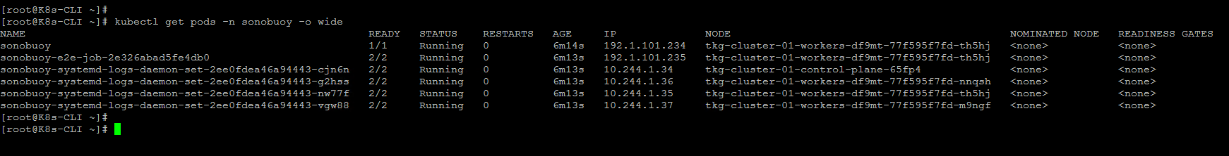
Login to the Tanzu Kubernetes cluster directly using CLI and verify.


You can see corresponding VMs in the Center UI.


Now, let's have a look at the NSX-T side.
  • A Tier-1 Gateway is now available with a segment linked to it.


  • You can see a server load balancer with one virtual server that provides access to KubeAPI (6443) of the Tanzu Kubernetes cluster that we just deployed.


  • You can also find a SNAT rule. This helps the Tanzu Kubernetes cluster objects to reach the external network/ internet. It uses the egress range 192.168.72.0/24 that we provided during the workload management configuration for address translation.

Note: This architecture is explained on the basis of vSphere 7 U1. In the newer versions there are changes. With vSphere 7 U1c the architecture changed from a per-TKG cluster Tier 1 Gateway model to a per-Supervisor namespace Tier 1 Gateway model. For more details, feel free to refer the blog series published by Harikrishnan T @hari5611.

In the next part we will discuss monitoring aspects of vSphere with Tanzu environment and Tanzu Kubernetes clusters. I hope this was useful. Cheers!

Sunday, April 18, 2021

vSphere with Tanzu using NSX-T - Part7 - Enable workload management

In the previous posts we discussed the following: 

Part1: Prerequisites

Part2: Configure NSX-T

Part3: Edge Cluster

Part4: Tier-0 Gateway and BGP peering

Part5: Tier-1 Gateway and Segments

Part6: Create tags, storage policy, and content library


We are all set to configure and enable workload management. Before stepping into the configurations I just want to give an overall picture of vSphere with Tanzu architecture and different components. 


Once you enable workload management, the vSphere cluster will transform to a supervisor cluster. The supervisor cluster consists of 3 supervisor control plane VMs, and the ESXi hosts that act as worker nodes too. Now you can run traditional VMs, and containers side by side. You can run the containers as native vSphere pods directly running on the ESXi hosts, or you can deploy Tanzu Kubernetes clusters in VM form factor on the vSphere namespace and then run container workload on them.

Following are the steps to enable workload management:

  • Login vCenter - Menu - Workload Management.
  • Click Get started.
  • Select NSX-T and click next.

  • Select the cluster.

  • Select a size and click next.

  • Select the storage policy and click next.

  • Provide management network details and click next.

  • Provide workload network details and click next.

  • Add the content library and click next.

  • Click finish.

  • This process will take few minutes to configure and bring up the supervisor cluster. In my case, it took around 30 minutes to complete.
  • You can see the progress in the vCenter UI.


  • You can now see the supervisor control plane VMs are deployed.


Workload management is now enabled and the vSphere cluster is transformed to a supervisor cluster. Let's have a look at the objects that are automatically created in NSX-T.
  • You can see a T1 Gateway is now provisioned.

  • Multiple segments are now created corresponding to each namespace inside the supervisor control plane.

  • Multiple SNAT rules are also now in place for the newly created T1 Gateway, which helps the control plane Kubernetes objects residing in their corresponding namespaces to reach the external network/ internet. It uses the egress range 192.168.72.0/24 that we provided during the workload management configuration for address translation.

  • You can also see two load balancers attached to the T1 Gateway:
    • Distributed Load balancer: All services of type ClusterIP are implemented as distributed load balancer virtual servers. This is for east-west traffic.
    • Server load balancer: All services of type Loadbalancer are implemented as server load balancer L4 virtual servers. And all ingress is implemented as L7 virtual servers.

  • Under the server load balancer, you can see two virtual servers. One for the KubeAPI (6443) and the other for downloading the CLI tools (443) to access the cluster.

Note that this newly created T1 Gateway (domain-c8:6ea515f0-39da-431b-93bf-0d6a5e4a0f77) is connected to the T0 Gateway for external connectivity through BGP.
 
The next step is to create namespaces, and you can then create Tanzu Kubernetes clusters on it. Usually, the vSphere administrator will create namespaces for developers and provide the access so that they can either deploy TKG clusters, vSphere pods, or VMs on the respective namespace. We will cover all these in the next part. 

Hope it was useful. Cheers!